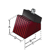
AWS探頭和楔塊


AWS探頭和楔塊符合美國焊接協會的結構焊接規范對用于焊縫檢測中的角度聲束組合件提出的特殊要求����。
Advantages
-
Transducers and wedges meet or exceed the specifications as set forth by the AWS Code Section D1.1
-
Snail wedges use industry accepted hole spacing
-
Captive screws included with the transducer
-
Accupath style wedges marked with a five line graticule to assist in locating the beam exit point
AWS Transducers
* Wedges are available in standard refracted shear wave angles of 45°, 60° and 70° in steel. Please specify upon ordering.
Snail Wedges

*Distance between screws (center to center) is 1.00".
Accupath Wedges
*Distance between screws (center to center) is 1.062".
CDS楔塊

CDS楔塊可在鋼材料中產生30度橫波和70度縱波,從而通過30-70-70技術對與內壁相連的裂縫進行定量�����。
Understanding CDS
The 30-70-70 crack detection technique uses a single element transducer with a CDS wedge for detection and sizing of ID connected cracks. This technique uses a combination of three waves for sizing flaws of different depths.
-
An OD creeping wave creates a 31.5 degree indirect shear, (red in diagram to the left), wave which mode converts to an ID creeping wave; this will produce a reflected signal on all ID connected cracks.
-
A 30 degree shear wave, (yellow in diagram to the left), will reflect off the material ID at the critical angle and mode convert to a 70 degree longitudinal wave; a signal will be received by the transducer on mid-wall deep cracks.
-
A 70 degree longitudinal wave, (blue in diagram to the left), will reflect off the tip of a deep wall crack.
Based on the presence or absence of these three waves, both detection and sizing of ID connected cracks is possible.

CDS Wedges
CDS Wedges are used in the "30-70-70" technique for crack detection and sizing. They are compatible with our replaceable miniature screw-in angle beam transducers, making them an economical alternative to other commercially available products.
Normal Incidence Shear Wave Transducers
Single element normal incidence Shear Wave Transducers contact transducers introduce shear waves directly into the test piece without the use of refracted wave mode conversion.
We recommend the use of our SWC shear wave couplant for general purpose testing.

Advantages:
-
Generate shear waves which propagate perpendicular to the test surface
-
For ease of alignment, the direction of the polarization of shear wave is nominally in line with the right angle connector
-
The ratio of the longitudinal to shear wave components is generally below -30 dB
Applications:
-
Shear wave velocity measurements
-
Calculation of Young's Modulus of elasticity and shear modulus (see Technical Notes, page 46)
-
Characterization of material grain structure
Transducer Configurator
Shear Wave Couplant